In the intricate world of robotics and physical simulation, the devil is often in the details. A well-designed robot can perform a wide array of tasks in the real world, but to do so accurately in a simulated environment, we need to pay close attention to one critical aspect: the collision mesh.
Understanding Collision Mesh for Robot
A collision mesh is a streamlined geometric model employed for physical simulation. Unlike the
visual mesh (the representation we observe on the screen), a collision mesh is utilized to detect
collisions and calculate contact between objects within a physics engine. In a .urdf file, the
collision mesh is defined within the <collision> tag, distinct from the visual mesh.
The precision of our collision mesh in mirroring the actual shape of the robot hand significantly influences the accuracy of our simulation's predictions and responses to interactions, thereby enhancing realism. However, the quest for a highly realistic collision mesh can demand substantial computational resources. Meshes with higher realism often contain more vertices and faces, which can notably increase the computational requirements for running the simulation. This could potentially slow down the simulation. Sometimes, it might be beneficial to ignore minor physical details in the simulation to simplify the problem.
Consequently, crafting a collision mesh for a robot is a non-trivial task. This complexity is especially amplified in the case of dexterous hands, which possess a much larger number of links compared to a robot arm. The task demands thorough attention and cannot be completely automated via scripting.
In this blog, we will navigate through this challenge. By utilizing a specific robot hand as example, we will illustrate the step-by-step process of creating collision mesh for a robot hand.
Example: Creating a Model for the SVH Hand
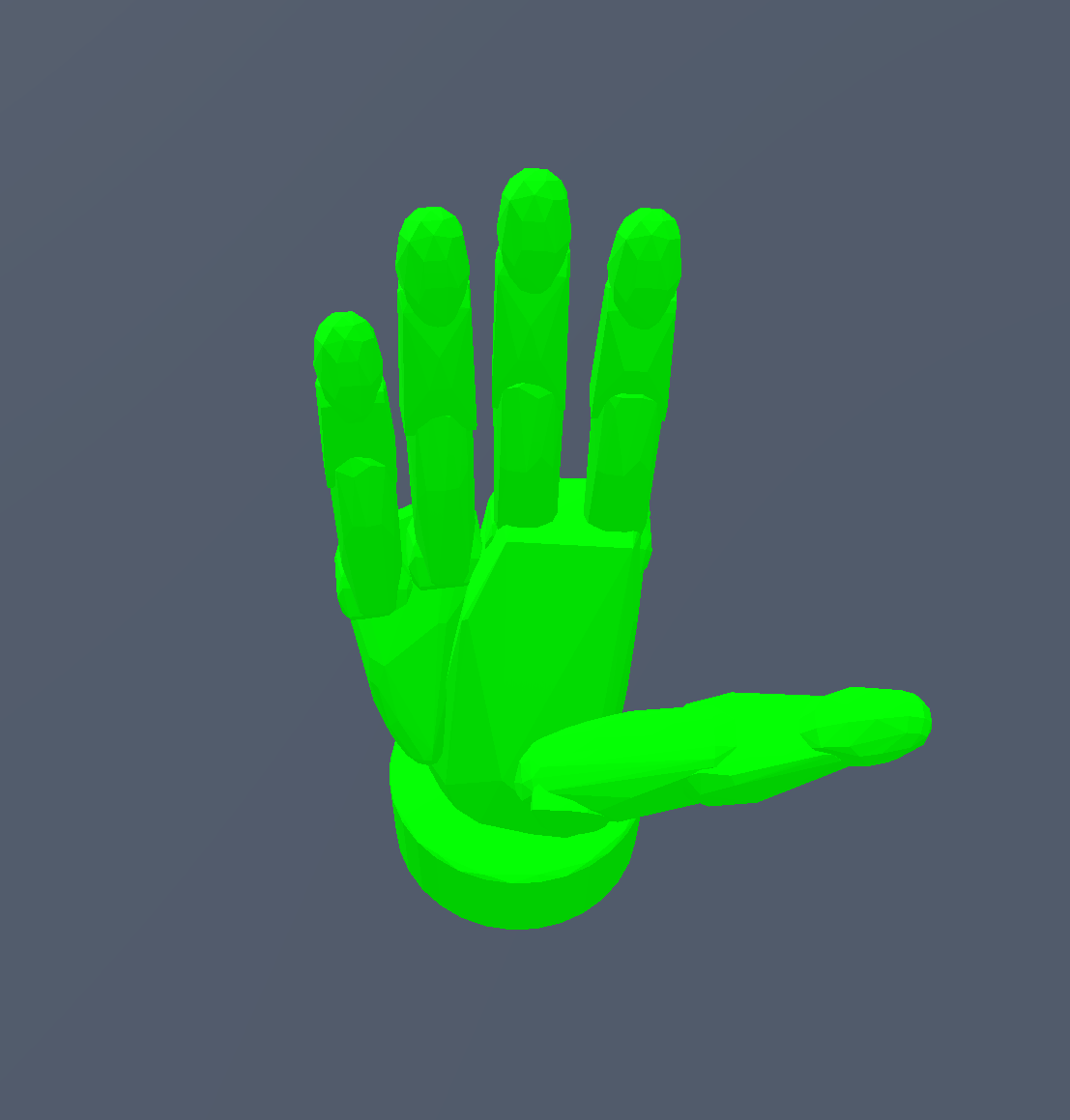
In this tutorial, we are going to walk you through a detailed process of creating a collision mesh model using the manufacturer-provided URDF, specifically for the SCHUNK SVH Hand. The original URDF from SCHUNK employs the same mesh file for collision as well as visual representation. This approach could lead to significant issues as many simulators often default to converting the imported collision mesh into a convex hull.
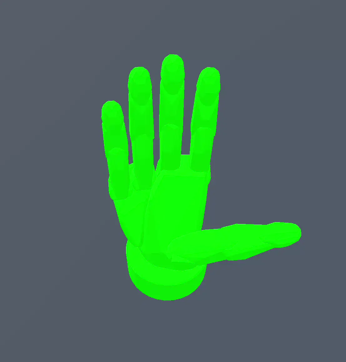
Below, we present the collision mesh derived from the original URDF. The left image depicts the original collision geometry, while the right one represents the contact force of self-penetration during motion. As you can intuitively imagine, loading this model directly into your simulator would lead to unpredictable behavior due to the self-collision causing random movement. The red arrow indicates the contact force, with deeper red signifying greater force. You can visualize this using the ContactViewer tool.
| Collision Mesh | Weired Motion from Self Collision |
|---|---|
 |  |
To address the problem identified above, we'll manually remodel the collision mesh. There are several methods for this, such as using primitives like a box or sphere for collision representation, employing convex decomposition derived from the visual mesh, or even designing a more tailored solution.
Building Collision Mesh: Single Primitive Approach
Let's start with the base, corresponding to base10.dae.
It's important to note that using a .dae file to represent a visual mesh can lead to
inconsistencies across different URDF parsers. This is why DexSuite does not use .dae files for
visual meshes. While this is not the main focus of this blog post, we thought it was worth
mentioning.
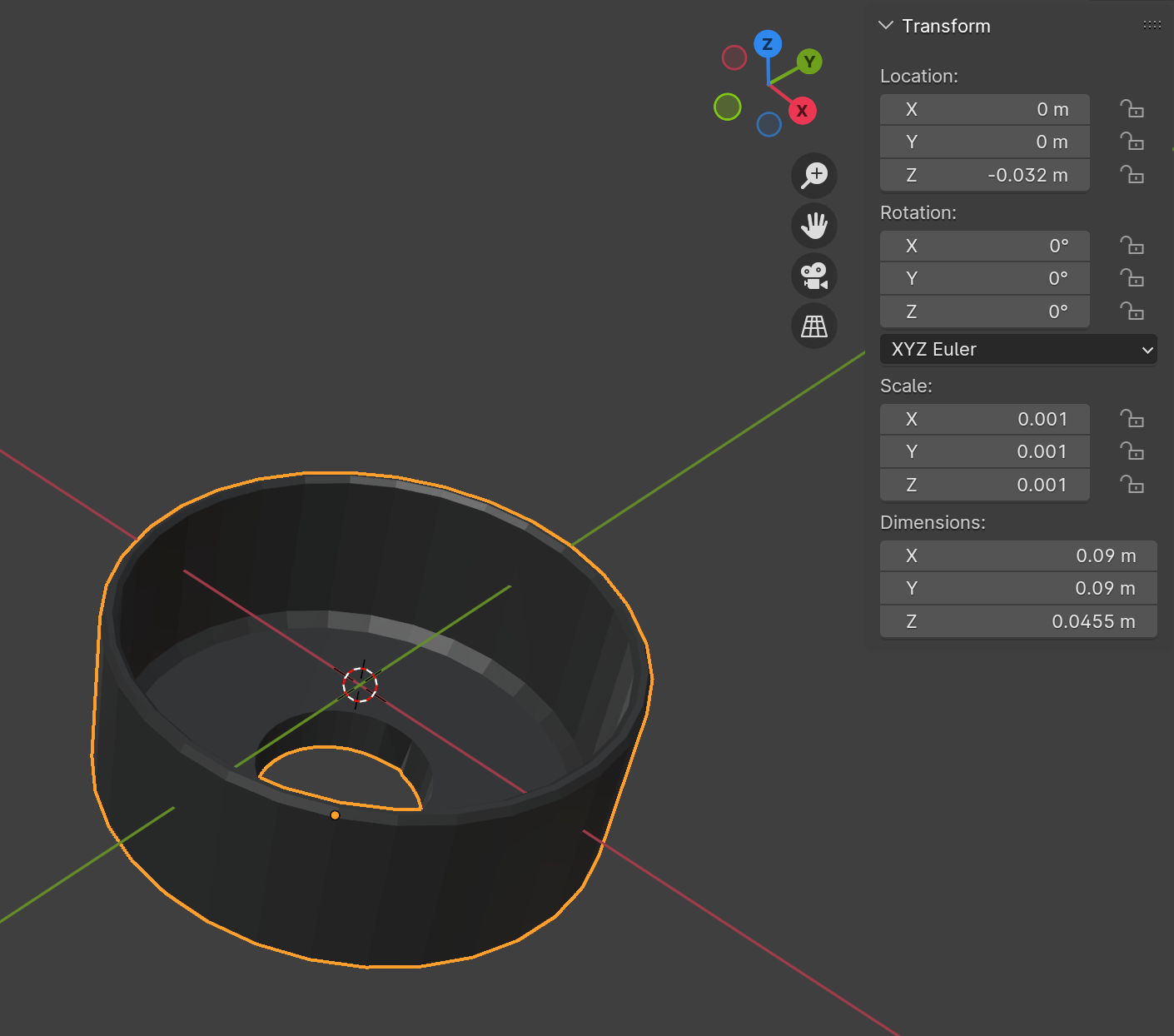
Next, import the visual mesh into your preferred graphics software, such as Blender. We notice that the shape of this mesh closely resembles a cylinder. Therefore, let's attempt to use a cylinder to represent the collision mesh. Usually, it's more efficient to use a primitive than a mesh file for collision representation.
<visual>
    <origin rpy="0 0 0" xyz="0 0 -0.032"/>
    <geometry>
        <mesh filename="package://schunk_svh_description/meshes/base10.dae"/>
    </geometry>
</visual>
Remember to position the visual mesh in Blender based on the pose tag within the URDF, which has
a z=-0.032 position. Then, create a cylinder primitive and adjust its size and position to align
with the visual mesh.
| Visual Mesh in Blender | Created Cylinder Primitive in Blender |
|---|---|
 | 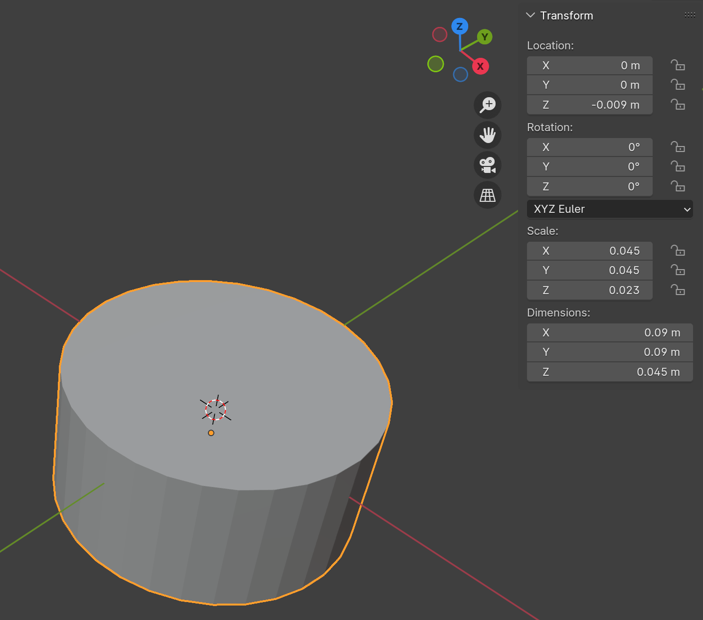 |
Afterward, we can copy-paste the cylinder information into the URDF as illustrated below. When you load the modified URDF into your simulator, the collision mesh will now be represented by a simple cylinder.
<link name="right_hand_base_link">
    <origin rpy="0 0 0" xyz="0 0 0"/>
    <visual>
        <origin rpy="0 0 0" xyz="0 0 -0.032"/>
        <geometry>
            <mesh filename="package://schunk_svh_description/meshes/base10.dae"/>
        </geometry>
    </visual>
    <collision>
        <origin rpy="0 0 0" xyz="0 0 -0.009"/>
        <geometry>
            <cylinder radius="0.045" length="0.045"/>
        </geometry>
    </collision>
</link>
Several simulators, like SAPIEN, IsaacGym, and IsaacSim, do not include a cylinder as a built-in
primitive. Hence, the URDF parser will interpret the cylinder as a triangle mesh internally. This
implies that for a cylinder, using a cylinder primitive in URDF or saving it as a mesh file will
yield identical results in simulation collision detection. However, for simplicity, we recommend
using the <cylinder> tag.
Building Collision Mesh: Multi Primitive Approach
Now, let's handle the palm, which corresponds to h10.dae and h11.dae. We'll begin with h10.
This part has a more complex structure than the previous ones, and it appears that a single
primitive cannot approximate it. Instead, we might need to use multiple primitives, such as three
boxes. You do not need to worry that the overlapping between different boxes since the collision
meshes of the same link will never collide each other.
| Visual Mesh in Blender | Created Box Primitives in Blender |
|---|---|
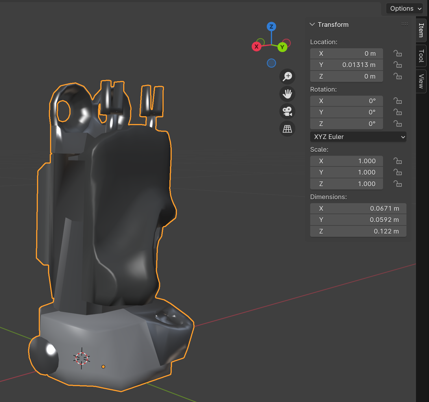 | 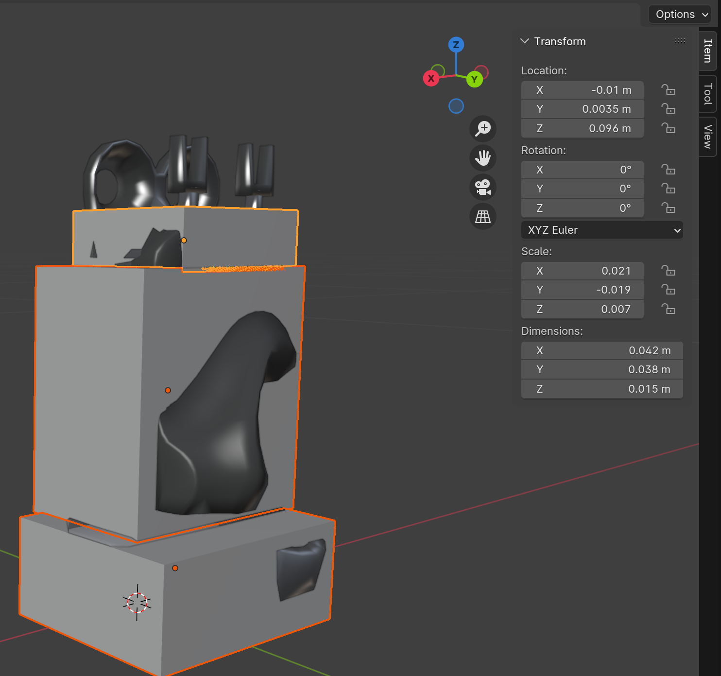 |
Why are some parts of the visual mesh not covered by the boxes, and why are others over-covered?
Over-coverage Reasoning: Typically, the collision mesh can be slightly larger than the actual shape for safety considerations. For instance, we expect our robot to manipulate objects with its fingers, not the hand base. The collision mesh for this part is primarily designed to prevent unwanted penetration, between the hand and the object, or between the hand and the robot arm.
Under-coverage Reasoning: For parts under-covered by the box, finger links are usually present, making these areas hard to reach for external objects. Moreover, the visual mesh does not represent the actual robot; it merely serves as a surrogate for its real counterpart that we do not need to follow precisely. In practice, modeling this uncovered part could lead to unwanted self-collision in the initial state.
Following the same design principle, we can also model the collision mesh corresponding to h11.
However, this is a complex design problem, and there isn't a unique solution for design. You'll
often find that the design choices are heavily dependent on your manipulation task with the robot
model. Remember, the modeling process is always iterative: you build collision meshes and put them
into a simulator to observe the outcomes. If something unexpected occurs, such as undesired
self-collision, you should update your collision mesh design.
When building models in DexSuite, we extensively
use simulation for motion checking
to enhance the modeling process.
Building Collision Mesh: Convex Mesh Approach
Let's now address the collision of index finger, is related to the URDF
links right_hand_virtual_l, right_hand_l, right_hand_p, and right_hand_t. We can
model right_hand_virtual_l as a spherical primitive using the aforementioned method. For the other
three meshes, we'll use convex decomposition.
Convex meshes are highly favored in physical simulations. Primitives such as spheres, boxes, cylinders, and capsules are all convex. To transform non-convex visual meshes into convex ones, we employ a process known as convex decomposition. This technique involves deconstructing complex, non-convex shapes into several simpler, convex shapes. It is an algorithmic process, eliminating the need for manual labor. More details about convex decomposition can be found in this article.
While primitives are ideal for efficient collision detection, they may not be the best representation for some robot links. Approximating these links with primitives could either use too many shapes or not accurately represent the actual link. This is especially true for links with frequent contacts, like fingertips, where the collision shape's alignment with the actual counterpart is crucial.
The CoACD tool is highly beneficial for performing convex decomposition. Here's a simple script to install CoACD and use it to generate decomposed meshes for the index finger links using default parameters:
pip3 install coacd
coacd -i f11.obj -o f11_collision.obj
coacd -i f12.obj -o f12_collision.obj
coacd -i f13.obj -o f13_collision.obj
For simple meshes such as the collision mesh of
an XArm link,
the default parameters work well. However, for f11, the default parameters produce overly complex
convex meshes. In such cases, we could consider using a smaller decomposition resolution, denoted
by -t. A larger value implies a lower granularity. More details on tuning these parameters can be
found on the original CoACD Github page.
coacd -i f11.obj -o -t 0.1 f11_collision.obj
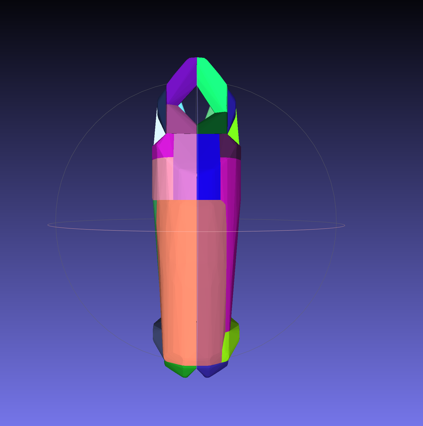
| Original Visual Mesh | CoACD with Default Params | CoACD with -t 0.1 |
|---|---|---|
| 1 SubMesh, 508 Vertices | 62 SubMeshes, 5083 Vertices | 29 SubMeshes, 3025 Vertices |
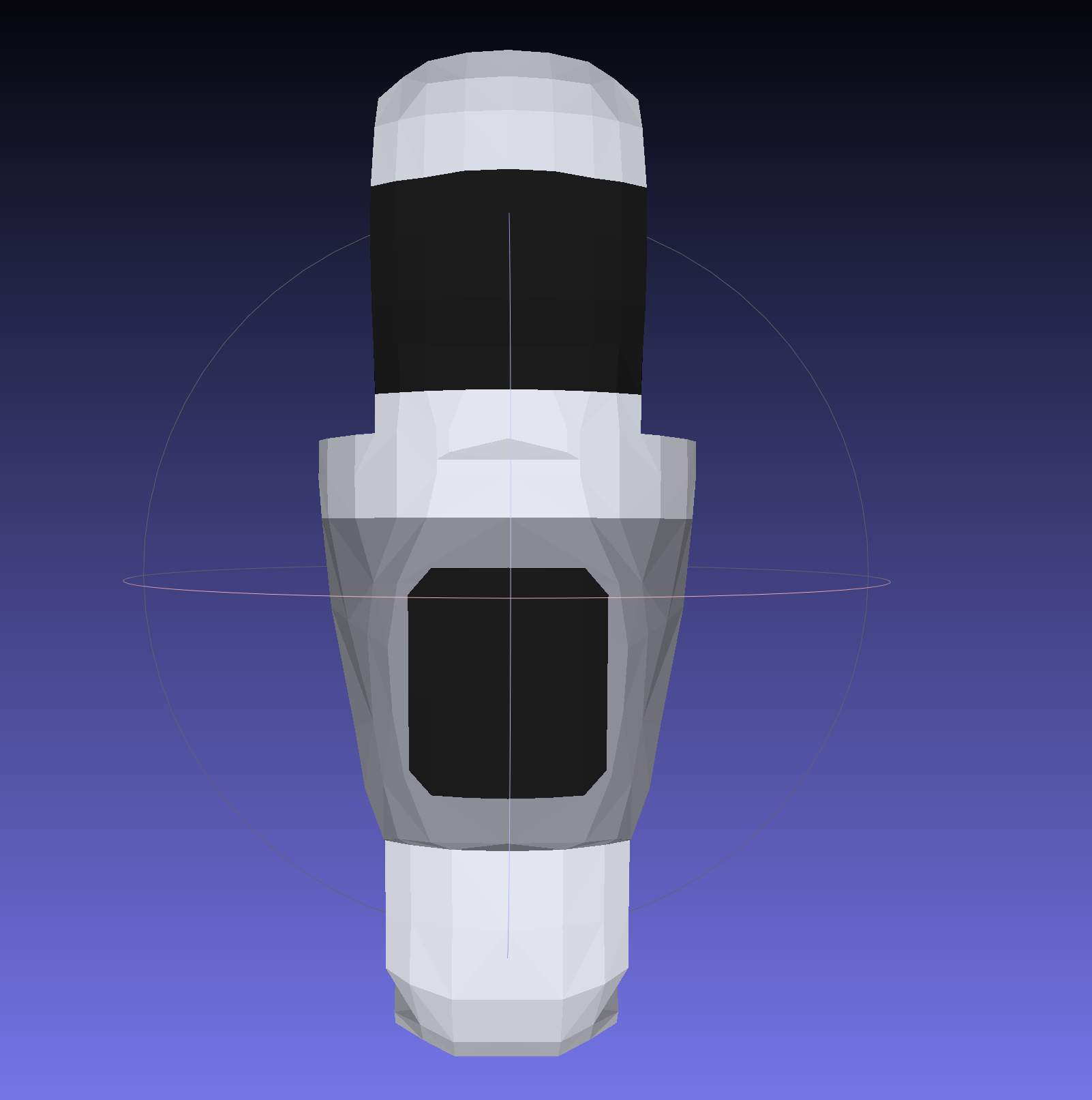 | 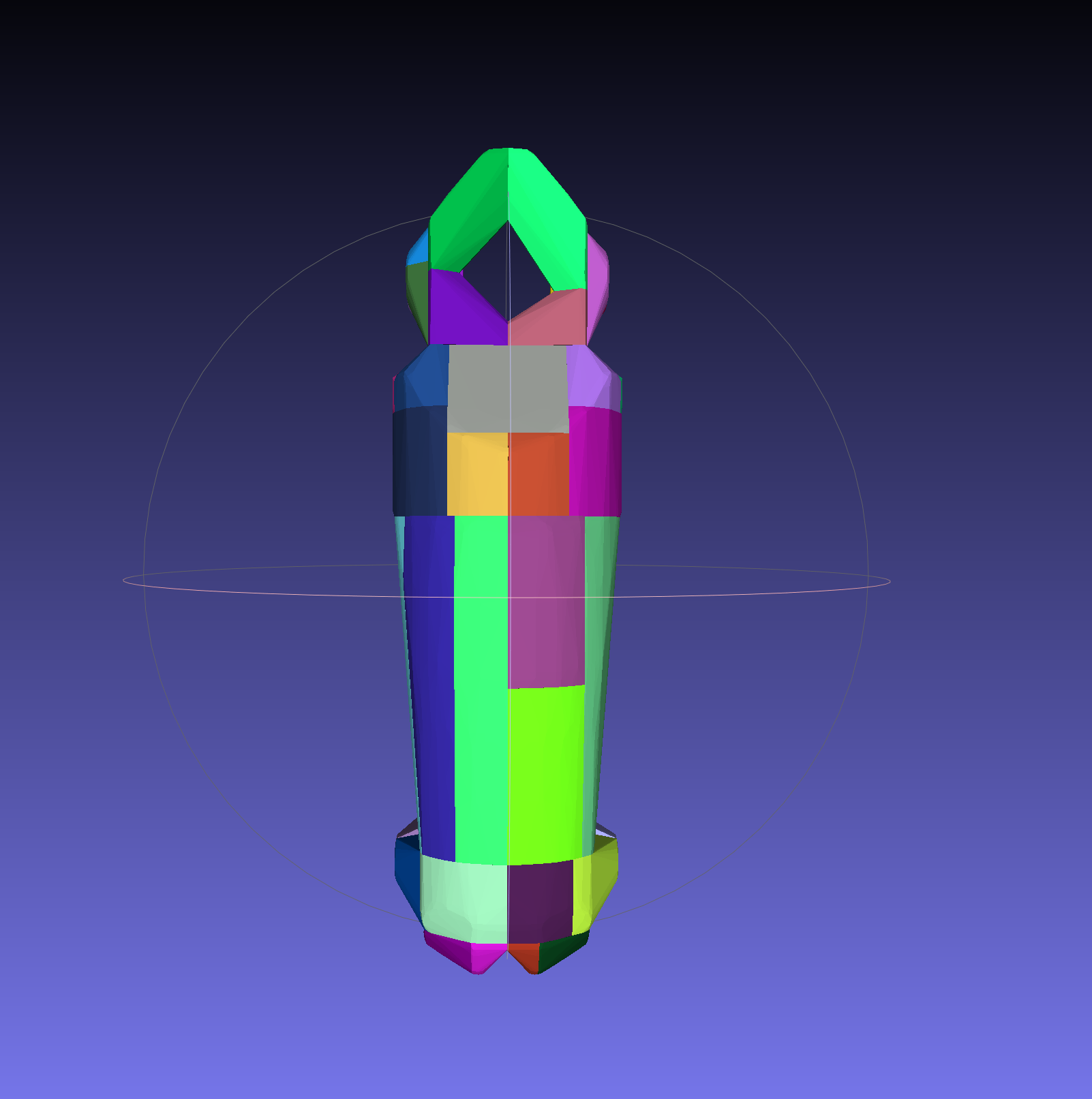 |  |
We can apply a similar method to create convex decompositions for other finger links. While this might seem adequate, you might find that your URDF model is experiencing intensive self-collision, even in its resting pose. So, what's the issue? We'll delve into this in the bext blog.
